
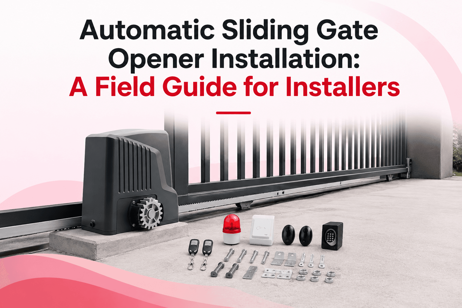
A sliding gate opener installs correctly when three things are true: the operator sits on a solid, level foundation; the pinion gear and the rack mesh with a consistent small gap along the full travel; and the limits and safety devices are set before the gate ever runs at full speed. Get those three right and the operator runs quietly for years. Get any one wrong and you get chatter, skipped teeth, false reversals, or a motor that overheats and fails early.
This guide walks through the full sequence a professional installer follows, the tolerances that actually matter, and the mistakes that cause the most call-backs. It applies to rack-and-pinion sliding operators on both ground-track and cantilever gates. Torque figures, gap tolerances, and limit types vary between operators, so always confirm the numbers against the manual for the specific model you are fitting.
Before you start: confirm the gate, not just the motor
Most failed installs are decided before the operator comes out of the box. The gate itself has to be right first.
A sliding gate should roll freely by hand end to end. If one person cannot push it smoothly through its whole travel with light effort, the operator will be fighting that resistance every cycle. Fix the gate before you automate it:
- The gate must be plumb and travel in a straight line, with no rise or dip along the run.
- Rollers, wheels, or cantilever trucks must be sound and correctly spaced. A worn bottom wheel or a seized top guide roller shows up later as a motor that "loses power" halfway.
- The stopping points at open and closed must be defined by physical stops, not by the operator alone.
- On cantilever gates, confirm the counterbalance length and truck spacing match the manufacturer's span before you commit the foundation position.
Sizing matters too. Match the operator's rated gate weight and length to the actual gate, and pick the duty cycle for the real traffic, not the average. A residential-rated unit on a busy shared driveway is the most common cause of premature failure. If you are still selecting the operator, our complete guide to sliding gate operators covers how span, weight, and duty cycle drive the choice.
Pre-installation checklist
Item | What to confirm |
Gate movement | Rolls freely by hand, straight, no binding across full travel |
Physical stops | Open and closed stops fitted and solid |
Operator rating | Gate weight and length within rated range; duty cycle suits traffic |
Power supply | Correct voltage available; dedicated, protected circuit planned |
Foundation area | Firm, drained ground clear of services; room for the operator and rack |
Safety devices | Photocells, and an edge or monitored device where required, on hand |
Step 1 - Pour or confirm the foundation
The operator needs a stable, level base that will not shift or heave. On most installs that means a concrete pad. Cast it with anchor bolts or a base plate positioned exactly where the manual specifies relative to the gate and the rack line — position is easier to get right in wet concrete than to correct afterward.
Two details save trouble later. First, keep the pad top at the height that puts the pinion at the correct meshing position for the rack you will mount; measure this from the rack line down, do not guess. Second, run the electrical conduit up through or beside the pad before the pour, so power and low-voltage cabling arrive without surface runs. Let concrete cure adequately before mounting a heavy operator and loading it.
Step 2 - Mount and level the operator
Set the operator on its base and get it level in both directions. A unit that leans throws the pinion out of parallel with the rack, which concentrates load on one edge of the gear teeth.
Position the operator so the pinion sits centrally under where the rack will run, at the correct depth. Most rack-and-pinion operators are designed for the rack to rest so its teeth engage the pinion with the gate's weight helping to keep them meshed — but with a defined clearance, not resting hard. Snug the mounting bolts enough to hold alignment while you fit the rack; final torque comes after alignment is confirmed.
Step 3 - Fit the gear rack and set the mesh
This is the step that separates a quiet operator from a noisy one. The goal is a consistent, small gap between the pinion teeth and the rack teeth along the entire travel.
- Release the operator's manual clutch so the gate moves freely by hand.
- Rest the first rack section on the pinion teeth and support it at the manufacturer's recommended gap — commonly around 1–2 mm of clearance between rack and pinion — using a spacer or the operator's own teeth as a rest, per the manual.
- Level the rack section, then fix it to the gate at that height.
- Roll the gate along by hand to bring the next section over the pinion. Butt it tightly to the previous section so the tooth pitch stays continuous across the joint — a gap or overlap at a joint causes a periodic clunk once per pass.
- Repeat to the end of the travel, checking the gap at several points as you go.
Two rules keep the mesh honest. Keep a small vertical gap everywhere so the rack never bears its full weight on the pinion, which would wear the gears and load the motor. And keep the rack parallel to the gate's line of travel so the gap does not open and close as the gate moves. When the rack is fully fitted, cycle the gate slowly by hand end to end and feel for any tight or loose spot; correct it before powering up. For why rack quality and drive type affect this over the long term, see our comparison of rack-and-pinion versus chain drive sliding operators.
Step 4 - Wire the power and ground the system
Connect the operator to a supply that matches its rated voltage on a dedicated, correctly protected circuit; a shared or undersized supply causes voltage drop that reads as weak or intermittent operation. Follow the manual's terminal diagram for the motor, control board, and any transformer.
Ground the operator properly. A gate operator sits outdoors on metal and benefits from both electrical grounding and, in exposed locations, surge protection — lightning-induced surges are a common killer of control boards. Keep low-voltage accessory wiring (photocells, keypads, loops) separate from mains wiring, and use the cable gauge and type the manufacturer specifies for the run length.
Step 5 - Set the travel limits
The limit system tells the operator where to stop opening and closing. Sliding operators typically use either magnetic limits (magnets on the rack triggering a sensor) or mechanical cam or lever limits — check which your model uses.
Set the closed limit so the gate reaches its physical closed stop without ramming it, and the open limit so it stops short of over-travelling off its rollers or into the backstop. Leave the operator to slow into each limit rather than hitting it at full speed; most controllers have a soft-stop or slowdown zone for this. After setting, run several full cycles and confirm the gate stops in the same place each time. Drifting stop points usually mean a loose limit magnet, a limit sensor mounted where the rack flexes, or a rack joint that is not tight.
Step 6 - Fit and test safety devices before final commissioning
Automatic gates carry real entrapment and impact risk, and this is not the step to shortcut. In the US, UL 325 requires monitored secondary entrapment protection on automatic gate operators; in the EU the relevant machinery and safety-device standards apply. Exact requirements depend on the destination market, the operator type, and the site, so specify to the standard that governs where the gate is installed, and document what you fitted.
In practice, effective protection for a sliding gate usually combines:
- Photocells (photo-eyes) across the opening at the pinch and travel points, positioned so a person or vehicle in the path stops the gate. Many sites need more than one pair to cover both the opening and the leading edge.
- A safety edge or other monitored device on the leading edge where crushing or shearing is possible, wired to the operator's monitored input where the standard calls for it.
- Loop detectors where free-exit or safety-reverse behaviour is needed for vehicles, sized and placed for the traffic.
Test every device by triggering it during motion and confirming the gate responds as required - stopping, reversing, or holding — before you hand the system over. A gate that closes on an obstruction because a photocell was aimed at the sky is a liability, not a finished job. For deeper detail on sensor wiring and anti-crushing setup, our guide to gate safety sensors and anti-crushing setup covers the principles that apply across gate types.
Step 7 - Commission, adjust force, and hand over
With limits and safety set, run the gate through its full cycle and tune the rest:
- Force and obstruction sensitivity: set the operator to move the gate reliably but reverse or stop on a real obstruction with modest resistance. Too high and it becomes dangerous; too low and wind or a slightly stiff gate causes nuisance stops.
- Speed and soft-stop: confirm the gate accelerates smoothly and slows into both limits.
- Accessories: program remotes, keypads, and any access control, and test each entry method.
- Manual release: show the owner how to disengage and move the gate by hand during a power loss, and confirm the release is accessible.
Finish by cycling the gate a dozen times under real conditions and listening. A correctly installed rack-and-pinion operator is quiet and even; recurring noise at the same point in travel almost always traces back to a rack joint or a mesh gap that needs correcting.
Ground-track vs cantilever: what changes at install
The operator and rack process is broadly the same, but the running gear differs and it affects the foundation and alignment.
Ground-track (V-track) | Cantilever | |
Support | Bottom wheels run on a track set in the ground | Rollers/trucks carry the gate on posts; no ground track |
Key install concern | Track must be straight, level, and drained; debris and ice on the track cause binding | Truck spacing and counterbalance length must match the span; posts must be solid |
Foundation note | Track and operator base both need stable ground | Post foundations carry the whole load and must not move |
Common fault | Track fouled by dirt, gravel, or ice | Sagging free end from wrong truck spacing or an undersized counterbalance |
Cantilever suits sites where a ground track is impractical or where snow, mud, or debris would foul a track. Ground-track systems can carry very heavy gates economically where the ground is suitable. Either way, the operator only performs as well as the running gear beneath the gate.
Common installation mistakes that cause call-backs
- Automating a gate that does not roll freely. The operator inherits every bit of friction. Service the gate first.
- Rack resting hard on the pinion. No clearance means gear wear and motor strain. Keep the small gap.
- Loose or misaligned rack joints. A single bad joint gives a once-per-pass clunk and can skip teeth.
- Operator not level. Edge-loads the gears and shortens their life.
- Limits set to slam the stops. Use the slowdown zone; hard hits loosen limits and damage the gate.
- Safety devices fitted but not tested, or aimed wrong. A photocell that never sees the path protects no one.
- Undersized or shared power supply. Voltage drop reads as an operator "losing power."
FAQs
How long does a sliding gate opener installation take?
For an installer working on a gate that already rolls well and has power nearby, a straightforward rack-and-pinion install is typically a few hours plus setting and testing safety devices. Foundation curing, running new power, or correcting the gate's running gear can extend it across two visits.
What gap should there be between the rack and the pinion?
A small, consistent clearance - commonly around 1–2 mm - so the teeth mesh without the rack bearing its full weight on the pinion. Confirm the figure in your operator's manual, and keep it even along the whole travel.
Do I need photocells and a safety edge, or is one enough?
It depends on the governing standard and the site. Photocells guard the path; an edge guards the leading edge against crushing. Many installations need both, and US installs under UL 325 require monitored secondary entrapment protection. Specify to the standard for the market where the gate is installed.
Can a sliding gate opener run on solar power?
Yes, where the duty cycle and climate suit it. Solar-ready operators pair a battery and panel sized for the daily cycle count and local sunlight, which makes them practical for rural and off-grid entrances.
Why does the gate stop or reverse partway? Usually an obstruction-sensitivity setting that is too tight for a slightly stiff gate, a fouled track, a mesh that tightens at one point, or a safety device triggering. Diagnose in that order rather than simply raising the force.
Bringing it together
A clean sliding gate opener installation is mostly discipline: prove the gate rolls freely, build a level foundation, set an even rack-to-pinion mesh, wire and ground it properly, then set limits and safety devices deliberately and test them under load. The tolerances are small but they are not mysterious, and holding them is what separates an operator that runs silently for years from one that generates service calls.
If you are specifying or sourcing sliding operators to install at volume, matching the operator, rack, and accessories as a complete, correctly rated system is where reliability starts. Explore our sliding gate operators and accessories or talk to our team about the right configuration for the sites you serve.

Explore Related Automation Systems
Looking for motors, hardware, or installation systems mentioned in this guide? Discover our factory-direct gate opener range:
All Gate Openers
Browse DC24V sliding, swing & barrier operators with full factory warranty.
Explore Products →Residential Gate Operators
Ultra-quiet, solar-ready sliding & swing gate motors for homes and villas.
Residential Solutions →Commercial Gate Systems
Continuous-duty operators for gated communities, business parks & parking.
Commercial Solutions →Industrial Heavy-Duty
High-torque motors engineered for gates up to 4,000 kg and logistics hubs.
Industrial Solutions →