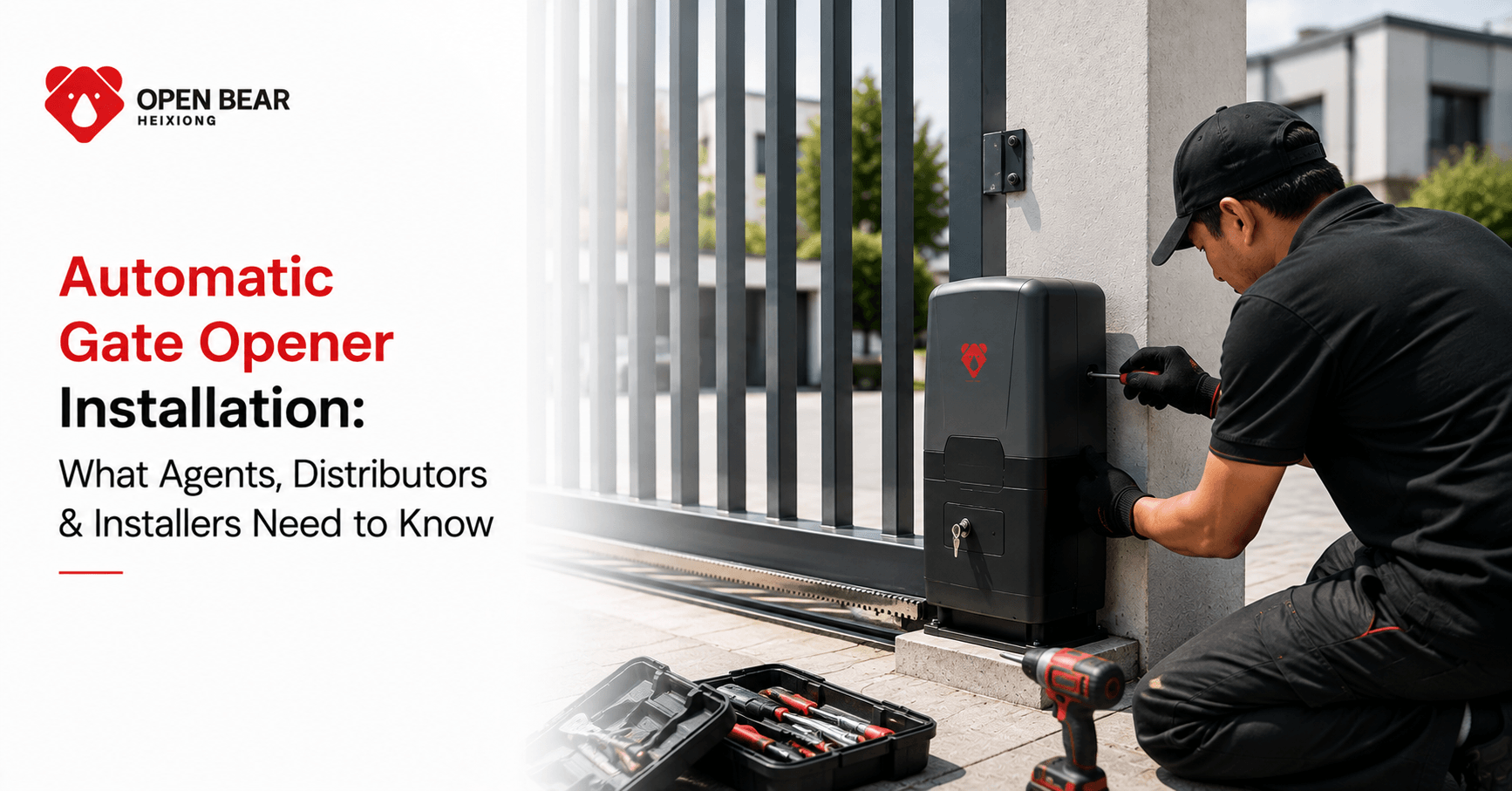
Every automatic gate opener installation has the same failure modes. Not because the product is wrong or the installer is incompetent — but because the same four steps get rushed or skipped on site, every time: arm geometry setup, limit switch calibration, safety device testing, and commissioning documentation. This guide is written for professional installers and the distributors supporting them. It covers what needs to happen at each phase of a swing gate operator installation and, more usefully, what goes wrong when it doesn't.
Pre-Installation: Site Assessment Before the Truck Arrives
Time spent on site assessment before installation day is not overhead — it's failure prevention.
Gate condition check: the gate must move freely by hand before the operator is installed. Not almost freely. Freely. A gate that requires 15 lb of push to start moving by hand will require that force on every motor cycle plus the inertia of the gate's weight. Over 30,000 cycles per year, that resistance degrades the motor, arm, and drive mechanism at a rate that shortens the service life from the rated 12–15 years to 4–6 years. Fix the gate first. New hinges, adjusted stops, repacked roller bearings — whatever is needed. Do not install an operator on a gate that doesn't move freely.
Post condition and suitability: for a side-mounted or column-mounted swing gate operator, the mounting post must be structurally sound. For masonry columns, probe mortar joints at the planned anchor locations. Soft or crumbling mortar reduces anchor pull-out capacity below what the operator's installation forces require. For steel posts, check for rust at the ground line — the most common failure point. The post must be vertically plumb; an out-of-plumb post changes the arm geometry relative to what the installation diagram specifies.
Power supply verification: confirm the circuit is the correct voltage, the correct amperage, and that the run length from the panel to the operator location is within the voltage drop tolerance for the wire gauge being used. A 14-gauge wire run over 150 feet on a 120V circuit drops enough voltage under motor load to cause erratic control board behavior — this presents as intermittent faults that are very difficult to diagnose after the fact.
Mounting clearance check: walk the full arc the gate will travel and confirm that nothing — vehicles, landscape features, drainage channels, other gates — is within the gate's arc plus 6 inches of clearance at the fully open position.
Phase 1: Mounting the Operator to the Post
The mounting position determines the arm geometry, and the arm geometry determines whether the operator delivers its rated force cleanly throughout the gate's arc or fights itself at certain positions.
The geometry diagram is not a suggestion. Every side-mounted swing gate operator ships with an installation diagram showing the exact relationship between the hinge centerline height, the operator pivot height, and the arm bracket position on the gate. These measurements are derived from the mechanical engineering of the specific arm mechanism and represent the position where force delivery is optimal throughout the full arc. Deviating from them — mounting 3 inches higher because the bracket landed more conveniently, or positioning the arm bracket lower on the gate because it was easier to drill — changes the force vectors and creates a system that either slams at full open, struggles through the last 20 degrees of close, or both.
Bracket installation on masonry columns:
- Use the manufacturer's specified anchor bolt size and embedment depth — not what's in the van from the last job
- Confirm pull-out rating of the specified anchor against the masonry condition
- Allow full cure time if epoxy anchors are used — typically 24 hours minimum at room temperature
- Torque mounting bolts to the specified value, not to feel
Bracket installation on steel posts:
- Through-bolt in preference to surface mount where post wall thickness allows
- If welding a plate: full perimeter weld, not tack welds, and confirm the post is grounded before welding near control wiring
- Verify the post is not going to deflect under the cyclic load the operator will apply over years of operation — hollow section posts with thin wall thickness can fatigue crack at the weld point
Phase 2: Arm Attachment and Length Setting
Once the operator is mounted, the arm is connected between the operator's output pivot and the bracket on the gate. The arm length setting is the most mechanically critical adjustment in the installation.
What arm length controls: the arm length determines where the gate stops at full open and what the force geometry looks like through the arc. Too short: the gate won't reach the programmed full-open position cleanly, and the motor fights the geometry at end-of-travel. Too long: the arm reaches its mechanical extension limit before the gate reaches the stop position, hammering the limit every cycle.
The correct setting: at full open, the arm should be extended but with 5–10mm of travel remaining before the mechanical hard stop. This buffer absorbs manufacturing tolerances and the small changes in gate geometry that occur as hinges wear over years of use.
At the closed position: the arm should hold the gate firmly against the gate stop with the gate latching cleanly. Test holding force by pushing the gate toward open with the operator powered and the gate in the closed position — the gate should not move.
For double leaf installations: set both arms to their respective geometries independently, then run synchronization tests before programming the limits. Do not program limits with one arm adjusted and the other at its factory default.
Phase 3: Wiring — Power, Control, and Safety Devices
Power wiring:
All 120V or 240V AC wiring must be in conduit — not exposed cable, not surface-run cable protected by trunking on a site exposed to vehicles or weather. Use conduit rated for outdoor use (PVC Schedule 40 minimum; galvanized steel for any run exposed to mechanical damage risk). The control enclosure entry point must be sealed against moisture ingress — silicone seal or appropriate conduit fittings with gaskets.
Control board low-voltage wiring:
Photo-eye sensors, keypads, loop detectors, and access control devices connect to the control board via low-voltage wiring (typically 12–24V DC). Keep low-voltage runs separate from 120V power runs — parallel routing creates induction interference that manifests as random false triggers on the control board inputs. The symptom is a gate that opens or reverses without an apparent command — which is difficult to diagnose unless you know to look at cable routing.
Photo-Eye Sensor Installation Guidelines
- Mounting Height: Install 4–6 inches above finished grade (bumper height).
- Alignment: Face sender and receiver directly opposite; a solid LED on the receiver confirms alignment.
- Cable Routing: Keep wiring separate from power lines; use shielded cable in high-interference areas.
- Protection: Use a minimum IP54 weatherproof housing and clean lenses monthly.
- Testing: Test the reversal function after every adjustment and prior to final commissioning.
Loop detector installation (where specified):
Vehicle loop detectors require embedding a wire loop in the driveway surface — typically a saw-cut channel filled with sealant after loop installation. The loop must be positioned so that a vehicle in the gate opening (not just approaching) is detected — preventing gate closure on a vehicle that hasn't fully cleared. Loop dimensions and inductance values should be confirmed against the loop detector unit's specification before installation.
Phase 4: Limit Switch Programming
Limit switches define where the operator stops the gate in the open and closed positions. Incorrect limit settings are responsible for more first-week callbacks than any other single cause.
Electronic limit learn procedure (most modern operators):
- With the arm connected but before the first powered cycle, manually position the gate at the fully closed position
- Initiate the closed-limit learn procedure per the operator's specific manual
- Manually position the gate at the full-open position (with 5–10mm of arm travel remaining)
- Initiate the open-limit learn procedure
- Run three full automated cycles and observe both stop positions precisely — the gate should arrive at each limit cleanly without the motor loading against the stop
Mechanical limit adjustment (older or budget units):
Physical limit switches inside the operator housing require adjustment with a screwdriver. Make one quarter-turn adjustments and test between each — the position sensitivity is higher than it appears, and over-adjustment at either end causes the gate to overtravel or stop short.
Anti-slam / deceleration programming:
Many commercial-grade operators include electronic deceleration — the motor reduces speed in the last 15–20 degrees of travel to prevent the gate hitting the stop at full speed. If this feature is present, verify it's active and set to an appropriate deceleration rate for the gate's weight. A heavy gate arriving at a hard stop at full motor speed creates impact loads on the arm, the gate stop hardware, and the mounting bracket that accumulate as fatigue damage over time.
Phase 5: Safety Device Testing — The Step That Cannot Be Skipped
UL 325 requires that safety devices be tested and verified before the installation is considered complete. This is not administrative compliance — it is the test that confirms a child or animal caught in the gate's path will not be injured.
Photo-eye reversal test procedure:
- Initiate a close cycle from a remote or keypad
- During the close cycle, break the photo-eye beam by walking through the beam path
- The gate must stop and reverse to full open within 2 seconds of beam interruption
- Repeat from both directions of approach to the beam
- If the gate does not reverse within 2 seconds: check sensor alignment, check wiring polarity, check control board sensitivity setting, retest. Do not leave the installation until this test passes reliably.
Inherent entrapment protection test:
- Place a 2x4 block flat on the ground in the gate's path during a close cycle
- The gate must stop and reverse upon contact with the block
- If contact detection sensitivity is adjustable, set it to the most sensitive position that doesn't produce false reversal during normal gate operation
Documentation: record the date, installer name, and test result for both safety device tests. This documentation is relevant for any future liability question regarding the installation.
Phase 6: Access Control Commissioning
Remote pairing:
Follow the control board's learn procedure precisely — the pairing sequence varies between manufacturers and often between product generations from the same manufacturer. Confirm each remote at maximum expected operating range, not just at arm's length from the control board.
Keypad programming:
Set the master access code and any secondary codes per the operator's programming guide. For commercial installations with multiple credential levels, confirm the programming against the access control matrix agreed with the site owner before leaving site.
Timer-to-close:
Set the auto-close delay appropriate for the site — long enough for a vehicle to clear the opening, short enough not to leave the gate open as a security risk. For vehicle gates, a minimum of 6 seconds after the gate reaches full open is typical; 15–30 seconds is common in commercial applications where delivery vehicles may need time to proceed. Test the timer with a vehicle in the gateway to confirm the gate does not close on the vehicle.
Commissioning Handover Checklist
- Mechanical & Geometry: Gate moves freely by hand with manual release engaged. Operator is mounted per geometry diagram with correct fastener torque, and arm length has a 5–10mm buffer at full open.
- Power & Wiring: Voltage, amperage, conduit, and sealed entries confirmed. Low-voltage wiring must be strictly separated from main power lines.
- Safety & Sensors: Photo-eyes are aligned with solid LED status and pass reversal tests (≤2 sec in both directions). Inherent entrapment test is fully verified.
- Limits & Speed: Limit switches are set for full open and full close (confirmed over 5 cycles), with the deceleration function active.
- Controls & Accessories: All remotes are paired and tested at range, keypads programmed, and the timer-to-close feature is tested with vehicle clearance.
- Power Backup & Handover: Battery backup verified via a manual power cut. Manual release operation is demonstrated to the site owner, with all manuals and warranty documents left on site.
About the Author
Leo Chen is a gate automation specialist and technical content writer with hands-on experience across residential, commercial, and industrial automatic gate operator systems. He covers UL 325 compliance, swing and sliding operator selection, access control integration, and installation best practices for gate industry professionals across the US market. His work is used by distributors, system integrators, and facility managers to make better-informed specification decisions. When he is not writing about gate automation, LEO works directly with installers and procurement teams to navigate product selection for complex commercial and industrial sites.

Frequently Asked Questions
Key engineering and selection answers regarding this topic
A single swing gate operator on a prepared post with power nearby takes an experienced installer 3–5 hours including mounting, arm setup, wiring, programming, and commissioning tests. A double leaf installation takes 6–10 hours. A commercial sliding gate installation with loop detectors, access control integration, and a new electrical circuit run takes 1–2 days depending on conduit length and site conditions. These are professional times — a first-time DIY installer should budget 50–100% longer. The critical insight is that installation time is dominated by mounting, geometry setup, and commissioning — not by the mechanical simplicity or complexity of the operator itself.
Photo-eye sensor misalignment is the leading cause of first-month callbacks, causing intermittent gate reversal or refusal to close. The second most common cause is limit switch mis-calibration — typically the closed limit set slightly short, causing the gate to stop 2–3 degrees before the gate stop and not latch properly. Both issues are preventable with a thorough commissioning process and are diagnosable in under 10 minutes by a competent installer. Third is remote range problems, almost always caused by the antenna wire coiled inside the control enclosure rather than extended externally. Extending the antenna wire to the outside of the enclosure resolves the range problem without any additional hardware.
The operators themselves are identical — the difference is in the bracket and anchor hardware. Column mounting on masonry requires masonry drill bits, appropriate anchor selection for the column material and condition, and knowledge of anchor pull-out ratings for the masonry type being worked with. This is not complex, but it requires attention to anchor specification that post mounting on steel does not. Steel post mounting requires either drilling and bolting (simple, no specialist trade) or welding a plate (requires a welder and appropriate site preparation). Neither is technically demanding for an experienced installer, but both require the right tools and the right preparation that aren't needed for the other.
Leave a written maintenance schedule covering: monthly — clean photo-eye sensor lenses, visually inspect arm connections and mounting hardware for any obvious movement; six-monthly — lubricate arm pivot points and any articulating joints with manufacturer-recommended lubricant, test battery backup by interrupting mains power, verify photo-eye reversal function; annually — full inspection including control board housing seal condition, wire connection integrity at all terminals, limit switch function check, gate hinge condition, and operational test of all access devices. For commercial installations with 60+ daily cycles, shorten the six-monthly tasks to quarterly. This schedule gives the site owner a clear responsibility framework and reduces warranty claims from deferred maintenance damage.
Explore Related Automation Systems
Looking for motors, hardware, or installation systems mentioned in this guide? Discover our factory-direct gate opener range:
All Gate Openers
Browse DC24V sliding, swing & barrier operators with full factory warranty.
Explore Products →Residential Gate Operators
Ultra-quiet, solar-ready sliding & swing gate motors for homes and villas.
Residential Solutions →Commercial Gate Systems
Continuous-duty operators for gated communities, business parks & parking.
Commercial Solutions →Industrial Heavy-Duty
High-torque motors engineered for gates up to 4,000 kg and logistics hubs.
Industrial Solutions →